
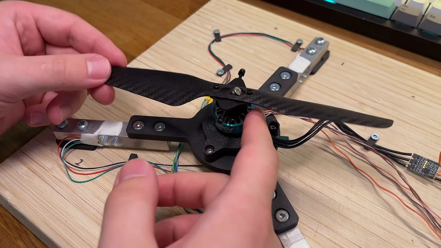
A maker who posts on YouTube as worked in theory has built a 3D printed micro helicopter rotor that changes its blade pitch with no swashplate and no servos. A single motor does all of it, steering the rotor by speeding up and slowing down within each turn. On a homemade test stand, the final version lifts about 140 grams at 5,500 RPM while drawing 29 watts.
The video, posted Monday, is the channel’s first and Part 1 of a series that is supposed to end with the helicopter flying on basic FPV gear. It did not start as a one-motor design. The maker’s first rotors adapted the wheeled swashplate inside the Black Hornet military nano drone, and friction dogged every version.
Friction Hobbled The Black Hornet Wheel Design, And Weight Ended It
The Black Hornet replaces a helicopter’s swashplate linkages with tiny wheels on the plate. The maker built three versions from its patent. The first locked the rotor when the plate tilted, the second stuck in neutral at speed and wore its wheels, and the third dragged on brass bushings.
The maker thought that third version was on the right track. The switch came down to weight. In the video, the maker says dropping the swashplate and its actuators saves grams on a helicopter meant to fly on basic FPV gear. The replacement, “at least for now,” is the hinged underactuated rotor that British YouTuber Tom Stanton, whose 3D printed windup plane DroneXL covered in April, has explored. Joshua Bird’s one-motor drone, which DroneXL covered on Tuesday, flies on the same principle.
A Single Center Hinge Beat Separate Blade Hinges
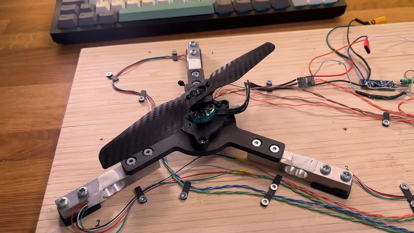
Run at about 3,000 RPM, the one speed where the dual-hinge rotor worked, a single center hinge gave more control authority and a faster response than a hinge on each blade. It also overshot the commanded pitch and resonated as inputs got faster.
The dual-hinge version gave no useful pitch below that speed, and above it hinge friction swamped the control signal. It also ignored small commands in a dead zone, which the maker blames on friction a better build could have reduced. Both rotors ran identical automated test sequences through load cells capped at 80 Hz by their HX711 amplifiers.
Standard PLA Beat The High-Temperature Blades On Stiffness
The final blade beats the maker’s first design, built in MATLAB with blade element theory, by 47% in lift and 26% in efficiency. Part of that gain came from the filament rather than the shape. The early blades were printed in Polymaker’s high-temperature PLA and bent under load.
Standard PLA proved stiffer, beat nearly every blade tested before it, and sent the maker back to rerun every earlier test. The blades are not printed in their final shape. A Fusion script the maker wrote unwraps each one into a flat blank and generates a mold that heat-presses it into its curve, which avoids the weak layer lines of a blade printed in 3D. The maker may release the script as an add-on if enough people ask.
Drag then twisted the finished blades off center. Small bolts and nuts added as balance weights pulled them back to neutral, and their inertia damped the rotor. In the final step test it settled on the command with barely any overshoot, and the resonance in the bandwidth test all but disappeared. SolidWorks flow simulation matched the measured lift almost exactly, while measured power ran higher, which the maker puts down to losses in the test setup.
Nothing has flown yet. The rotor has only run on the stand, and the video gives no target weight for the finished helicopter or says how it will counter the rotor’s torque.
DroneXL’s Take
I like where this maker landed, because the rotor is now the cheap part and the electronics carry the difficulty, and electronics are where a builder who wrote a blade generator in a couple of days is strongest. The custom PCB in Part 2 has to prove that. Steering this rotor takes one speed pulse per revolution, and at 5,500 RPM that is roughly 92 pulses a second. A standard drone ESC lost sync above 50 a second on Bird’s drone, and Bird ended up on a $94 servo drive that reads rotor position from a magnetic encoder. My guess is this board needs the same kind of position sensing, and that is the first thing I’ll look for in Part 2.
Source: worked in theory on YouTube
DroneXL uses automated tools to support research and source retrieval. All reporting and editorial perspectives are by Haye Kesteloo. Read our editorial standards.


